Abstract
This article explores the engineering principles, applications, and design strategies behind Complex 5 Axis CNC Machining Parts. It examines how simultaneous motion control enables the production of geometries that are impossible on conventional three-axis machines. The discussion covers material selection, tolerance management, industry applications in aerospace and medical sectors, and the critical design guidelines that ensure manufacturability. Practical insights for engineers evaluating suppliers are also provided.
Table of Contents
- Understanding the Core Mechanics of 5-Axis Machining
- Simultaneous vs. Indexed Machining: What Is the Difference?
- Materials and Their Impact on Machining Strategy
- Achieving Precision: Tolerances and Surface Finish
- Design Guidelines for Manufacturability
- Industry Applications and Case Insights
- Evaluating a 5-Axis Machining Partner
- Frequently Asked Questions
Understanding the Core Mechanics of 5-Axis Machining
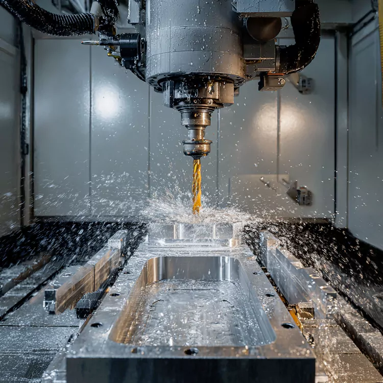
The foundation of modern precision manufacturing rests on the ability to move cutting tools in multiple directions simultaneously. A Complex 5 Axis CNC Machining Parts operation represents the pinnacle of this capability, adding two rotational axes to the conventional X, Y, and Z linear movements. This configuration allows the cutting tool to approach the workpiece from virtually any angle without the need for repeated repositioning.
On a standard three-axis machine, the workpiece remains fixed while the tool moves along three perpendicular axes. Accessing multiple faces of a component requires manual repositioning, which introduces cumulative errors and extends cycle times. Five-axis machining eliminates this constraint by introducing rotary motion that can tilt and rotate either the spindle head, the worktable, or both.
The Two Rotary Axes Explained
The additional axes are typically designated as A, B, and C, with two of these being active depending on the machine configuration. The A-axis rotates around the X-axis, the B-axis rotates around the Y-axis, and the C-axis rotates around the Z-axis. A trunnion-style machine, for example, might use A and C axes to tilt and rotate the workpiece, while a swivel-head design might use B and C axes to orient the cutting tool.
This mechanical capability translates directly into manufacturing advantages. When a part requires undercuts, deep cavities, or complex freeform surfaces, the tool can maintain an optimal contact angle with the material throughout the cutting path. This not only improves surface quality but also extends tool life by distributing wear more evenly across the cutting edge.
Key insight: The continuous adjustment of tool orientation is what separates five-axis machining from simpler multi-axis setups. The machine controller must calculate and synchronize the movement of all five axes in real time to follow a precise toolpath while avoiding collisions.
Simultaneous vs. Indexed Machining: What Is the Difference?
Within the realm of five-axis technology, two distinct operational modes exist. Understanding the difference is critical when specifying requirements or evaluating a supplier's capabilities.
Simultaneous 5-Axis Machining
In simultaneous mode, all five axes move together during the cutting process. The rotary axes do not lock into position while material is removed; instead, they continuously adjust to maintain the desired tool orientation relative to the surface being machined. This approach is essential for geometries with continuously changing curvature, such as turbine blades, impellers, and orthopedic implants.
The controller must coordinate linear and rotary movements with extreme precision. Even a small angular change at the rotary axis can translate into significant movement at the tool tip, especially when the tool assembly has substantial length. Accurate kinematic data and real-time compensation are therefore indispensable.
3+2 Axis (Indexed) Machining
Indexed machining, often called 3+2, positions the rotary axes at fixed angles and then performs cutting with only the three linear axes moving. The rotary axes remain stationary during the actual cut. This method offers greater stability and simpler programming than simultaneous machining, making it suitable for parts with planar features at various orientations.
| Feature | Simultaneous 5-Axis | 3+2 Axis (Indexed) |
|---|---|---|
| Axis Movement During Cut | All five axes move together | Rotary axes fixed; only X, Y, Z move |
| Best Suited For | Freeform surfaces, impellers, blades | Angled planar faces, prismatic parts |
| Programming Complexity | High; requires advanced CAM and simulation | Moderate; similar to 3-axis with indexing |
| Machining Stability | Lower due to continuous rotary motion | Higher; rigid setup during cutting |
| Surface Finish Capability | Excellent on curved surfaces | Excellent on flat and stepped surfaces |
Not every supplier that advertises five-axis capability is proficient in both modes. Simultaneous machining demands a deeper understanding of machine kinematics, post-processor development, and collision avoidance. When a project involves complex freeform geometry, verifying a supplier's simultaneous machining experience is essential.
Materials and Their Impact on Machining Strategy
Material selection shapes every aspect of the machining process, from cutting parameters to tool selection and fixturing strategy. Five-axis machining is compatible with a broad spectrum of materials, but each presents distinct challenges.
Aluminum Alloys
Aluminum is among the most machinable metals for five-axis operations. Grades such as 6061 and 7075 offer an excellent balance of strength, weight, and machinability. The 7075 alloy, often described as "super aluminum," provides significantly higher tensile strength than 6061, making it a preferred choice for aerospace structural components where weight reduction is critical.
Titanium and Nickel Alloys
Titanium alloys, particularly Ti-6Al-4V, and nickel-based superalloys like Inconel are essential in aerospace and medical applications due to their exceptional strength-to-weight ratios and corrosion resistance. However, these materials generate substantial heat during cutting and tend to work-harden, requiring sharp tooling, optimized coolant delivery, and conservative cutting parameters.
Stainless Steels and Tool Steels
Stainless steel grades including 17-4 PH and 316L are common in medical devices and food processing equipment. Their high toughness and low thermal conductivity demand careful chip evacuation and effective cooling. Tool steel and hardened alloys further increase the difficulty, often requiring specialized carbide or ceramic tooling.
Engineering Plastics and Composites
Materials such as PEEK, POM, PTFE, and carbon fiber composites are increasingly specified for weight-sensitive applications. These materials introduce their own challenges, including heat sensitivity, delamination risk, and the need for sharp, polished cutting edges to prevent fiber pull-out or surface melting.
- Aluminum alloys: excellent machinability, widely used for structural components
- Titanium alloys: high strength, heat-resistant, challenging to machine
- Stainless steels: corrosion-resistant, tough, require careful chip management
- Nickel superalloys: extreme temperature resistance, low machinability
- Engineering plastics: lightweight, heat-sensitive, require sharp tooling
- Composites: high strength-to-weight ratio, prone to delamination
Achieving Precision: Tolerances and Surface Finish
The value of five-axis machining lies not merely in its ability to create complex shapes but in doing so with extraordinary precision. Tolerances achievable on well-maintained five-axis machines routinely reach ±0.005 mm (±0.0002 inches) on critical features.
Why Single-Setup Machining Improves Accuracy
Every time a workpiece is repositioned on a machine, the potential for error increases. Fixture wear, clamping inconsistencies, and human factors all contribute to positional deviations. By machining multiple faces in a single setup, five-axis technology eliminates this error source. The relationship between features machined in the same setup is inherently more accurate because it is established by the machine's kinematics rather than by external positioning.
This principle is particularly important for parts with tight geometric tolerances, such as mating surfaces, bearing bores, and sealing faces. A housing component with multiple mounting pads at different angles, for example, can be completed without the cumulative stack-up errors that would accompany multiple setups on a three-axis machine.
Surface Finish Considerations
Surface finish in five-axis machining is influenced by toolpath strategy, tool geometry, cutting parameters, and the rigidity of the setup. When the tool is maintained at an optimal angle to the surface, the effective cutting speed at the tool tip remains more consistent, reducing witness marks and improving uniformity.
| Parameter | Typical Range | Factors Influencing Result |
|---|---|---|
| Dimensional Tolerance | ±0.005 mm to ±0.05 mm | Machine accuracy, thermal stability, fixturing |
| Surface Roughness (Ra) | 0.4 µm to 3.2 µm | Toolpath, tool condition, spindle speed |
| Angular Tolerance | ±0.01° to ±0.1° | Rotary axis calibration, kinematic model |
| Positional Tolerance | ±0.005 mm to ±0.02 mm | Machine geometry, probe calibration |
Note: Tighter tolerances are achievable on specific features but may require additional inspection, slower feed rates, or specialized tooling. Over-specifying tolerance on non-critical dimensions increases cost without functional benefit.
Design Guidelines for Manufacturability
Designing for five-axis machining requires a balance between functional requirements and manufacturing practicality. While the technology expands the realm of what is possible, certain principles still govern efficient production.
Feature Alignment and Tool Access
Aligning features with the machine's primary axes simplifies programming and reduces the demand on rotary motion. Although five-axis machines can reach features at arbitrary angles, aligning planar features with X, Y, or Z reduces cycle time and improves surface quality. This guideline should be treated as a recommendation rather than a rigid rule, as the capabilities of the machine may justify alternative approaches.
Wall Thickness and Cavity Depth
Thin walls and deep cavities present challenges in any machining operation. In five-axis work, the risk of deflection and vibration increases when the tool must reach deep into a cavity or machine a wall with limited support. Increasing wall thickness where possible, opening cavity geometry, or using stepped designs can improve rigidity and reduce the need for specialized tooling.
Tool Selection and Accessibility
The cutting tool must be able to reach the feature without colliding with other parts of the workpiece or fixture. This consideration is particularly relevant for internal features and undercuts. CAM software can simulate toolpaths and detect collisions, but early consideration of tool access in the design phase prevents costly redesigns later.
- Align features with primary axes where possible
- Avoid excessively deep cavities with narrow openings
- Design wall thickness to withstand cutting forces
- Consider tool length-to-diameter ratios for deep features
- Use radii in internal corners to match standard tool sizes
- Verify tool access during the design phase, not after
Industry Applications and Case Insights
The demand for complex five-axis machined components spans multiple high-technology sectors, each with its own performance requirements and material preferences.
Aerospace Components
Aerospace manufacturing relies heavily on five-axis machining for structural components, engine parts, and flight control surfaces. Turbine blades, impellers, and blisks require the simultaneous motion capability to achieve the aerodynamic surfaces and thin-walled geometries that maximize efficiency. Materials such as titanium alloys and nickel superalloys are common, demanding specialized tooling and cutting strategies.
Fuselage components and wing structural elements also benefit from five-axis machining. The ability to machine large, complex shapes in a single setup reduces assembly errors and improves the fit of mating parts.
Medical Devices and Implants
Orthopedic implants, surgical instruments, and dental components require the highest levels of precision and surface quality. Five-axis machining enables the production of patient-specific implants with complex porous structures that promote bone ingrowth, as well as instruments with intricate geometries that would be impossible to manufacture otherwise.
Titanium and its alloys are the dominant materials in this sector, valued for their biocompatibility and mechanical properties. The surface finish of implant components must meet strict standards to minimize the risk of bacterial adhesion and to ensure proper integration with surrounding tissue.
Automotive and Motorsport
High-performance automotive components, including cylinder heads, transmission housings, and turbocharger parts, benefit from the precision and surface quality achievable with five-axis machining. The motorsport industry often pushes the boundaries of design complexity, requiring rapid turnaround of components with organic, optimized geometries.
Robotics and Automation
Robotic joints, end-effectors, and structural frames require lightweight, rigid components with complex geometries. Five-axis machining enables the integration of features that would otherwise require assembly, reducing part count and improving system reliability.
Evaluating a 5-Axis Machining Partner
Selecting the right manufacturing partner is as important as the design itself. Not all suppliers that claim five-axis capability can deliver the precision and surface quality that complex parts demand.
Experience with Similar Geometries
The most reliable indicator of a supplier's suitability is their experience with components of comparable complexity. A company that regularly produces impellers or medical implants possesses different expertise than one that primarily machines simple brackets or plates. Requesting examples of similar work provides insight into their capabilities.
Machine Technology and Metrology
The machine tool itself is only part of the equation. The measurement equipment used to verify the finished part is equally important. Coordinate measuring machines (CMMs), in-process probing systems, and structured light scanning are all valuable tools for ensuring that complex geometries meet specification.
CAM Programming and Simulation
Advanced CAM software capable of generating efficient five-axis toolpaths is essential. Simulation and verification tools that detect collisions and gouges before machining begins save time and prevent costly errors. A supplier that relies on outdated programming methods or lacks simulation capability may struggle with complex projects.
Honmor maintains state-of-the-art manufacturing capabilities and a proven track record of delivering precision components across aerospace, medical, and industrial sectors. Contact us to discuss your project requirements and receive a comprehensive evaluation.
Frequently Asked Questions
Three-axis machining moves the cutting tool along three linear axes: X, Y, and Z. Five-axis machining adds two rotational axes, allowing the tool to approach the workpiece from multiple angles without repositioning. This enables the production of complex geometries, reduces setup time, and improves accuracy by eliminating errors from multiple clampings.
Yes. Five-axis machines routinely achieve tolerances of ±0.005 mm (±0.0002 inches) on critical features. The single-setup capability is a major contributor to this precision, as it eliminates the positional errors that accumulate when a part is moved between operations. However, achieving such tolerances requires proper machine maintenance, thermal stability, and careful process planning.
Most machinable metals, engineering plastics, and composites can be processed on five-axis machines. Common materials include aluminum alloys, titanium alloys, stainless steels, nickel superalloys, PEEK, POM, and carbon fiber composites. Material selection influences cutting parameters, tooling, and fixturing strategy, so it should be considered early in the design process.
In simultaneous machining, all five axes move together during the cut, allowing continuous adjustment of tool orientation to follow complex surfaces. In 3+2 (indexed) machining, the rotary axes are positioned at fixed angles and locked while the three linear axes perform the cutting. Simultaneous machining is necessary for freeform surfaces, while 3+2 is often sufficient for parts with angled planar features.
While five-axis machining expands the range of achievable geometries, some features remain challenging. Very deep, narrow cavities with limited tool access, extremely thin walls that are prone to vibration, and internal features that cannot be reached without excessive tool overhang are examples. Design optimization, such as opening cavity geometry or adjusting wall thickness, can often mitigate these challenges.
Surface finish is typically specified using the Ra (roughness average) parameter, measured in micrometers or microinches. In five-axis machining, achievable finish depends on toolpath strategy, tool condition, and machine stability. Typical values range from Ra 0.4 µm for fine finishing to Ra 3.2 µm for more general purposes. Surface finish should be specified only where functionally necessary, as tighter requirements increase cost and processing time.
A complete request should include 3D CAD models in a standard format such as STEP or IGES, 2D drawings with critical tolerances and surface finish requirements, material specification, quantity, and any special handling or inspection requirements. Providing information about the part's function and critical features helps the manufacturer optimize the process and identify potential manufacturing issues early.
Ready to bring your most complex component designs to life? Our engineering team is prepared to evaluate your requirements and recommend the optimal machining strategy.
Get a Quote →